
by Mara Klebonas
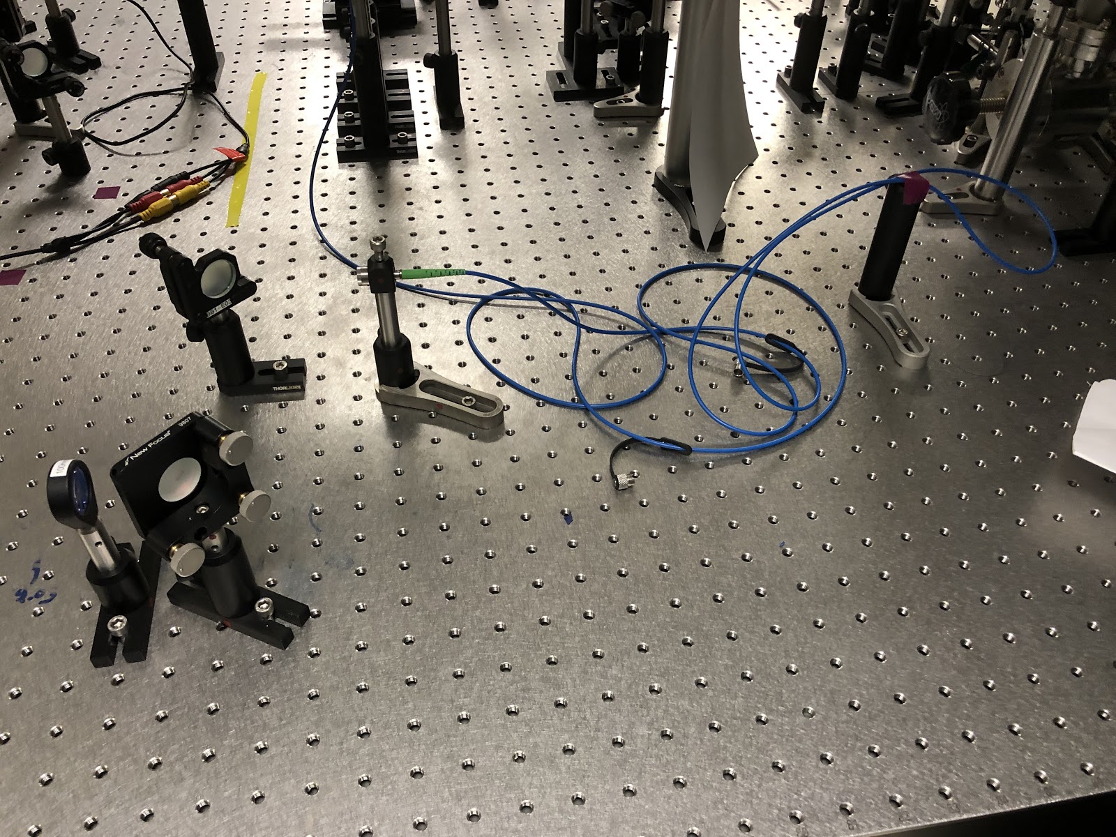
While reconstructing our MOT this past week, I ran into an issue aligning one of the polarization maintaining (PM) fibers used within our circuit. After ensuring the power meter was positioned correctly and secured to the optical table, I noticed that there was still a large fluctuation in power being detected. Essentially, this variance in incoming power indicated that the laser was not aligned to the correct polarization axis. Professor Wright had brought to my attention that there is a key on the cable itself that lines up with the slow axis of the fiber and should be perpendicular to the table, a detail so small but makes all the difference (and is a great example of one of the many things I have learned from hands-on experience in the lab!) Even though I had physically aligned the optical fiber with high efficiency, it was still misaligned to and was experiencing the natural change of the fast axis of the fiber.
I tried to align it with the key. After positioning the key correctly and rewalking the laser, I placed a half wave plate before the section of the circuit containing the PM fiber seeing as it is an essential optical component necessary to align the polarization axis. Didn’t work though. ???
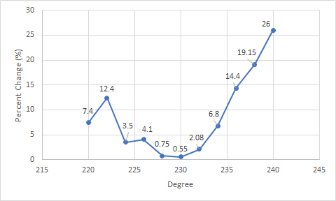
We tried a method for alignment previously not attempted in the lab before: taping a section of the fiber to a post holder. When tapping the fiber optic cable gently, it should not produce variance in the power reading when aligned to the correct polarization. Taping the fiber allowed me to achieve a more accurate reading. By adjusting the half waveplate’s angle, I was able to methodically record the change in power readings whilst the effect of the tapping occurred (e.g., the variance). Whichever angle on the waveplate produced the smallest fluctuation when the PM fiber was tapped was the best alignment for the polarization. Our lucky number is 230 degrees where there is a 0.55% change.
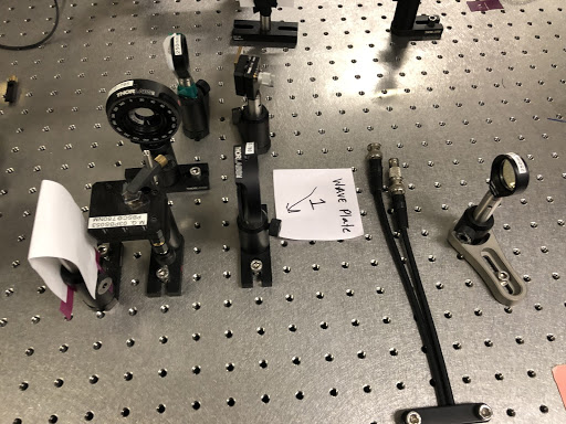
Here is the wave plate we added to align the polarization, shown as “Wave Plate 1”



Leave a Reply