

This website is really nice for understanding what happens in an resistance ladder:
Lets look a little deeper. I build the circuit in a simulator (https://www.circuitlab.com/)
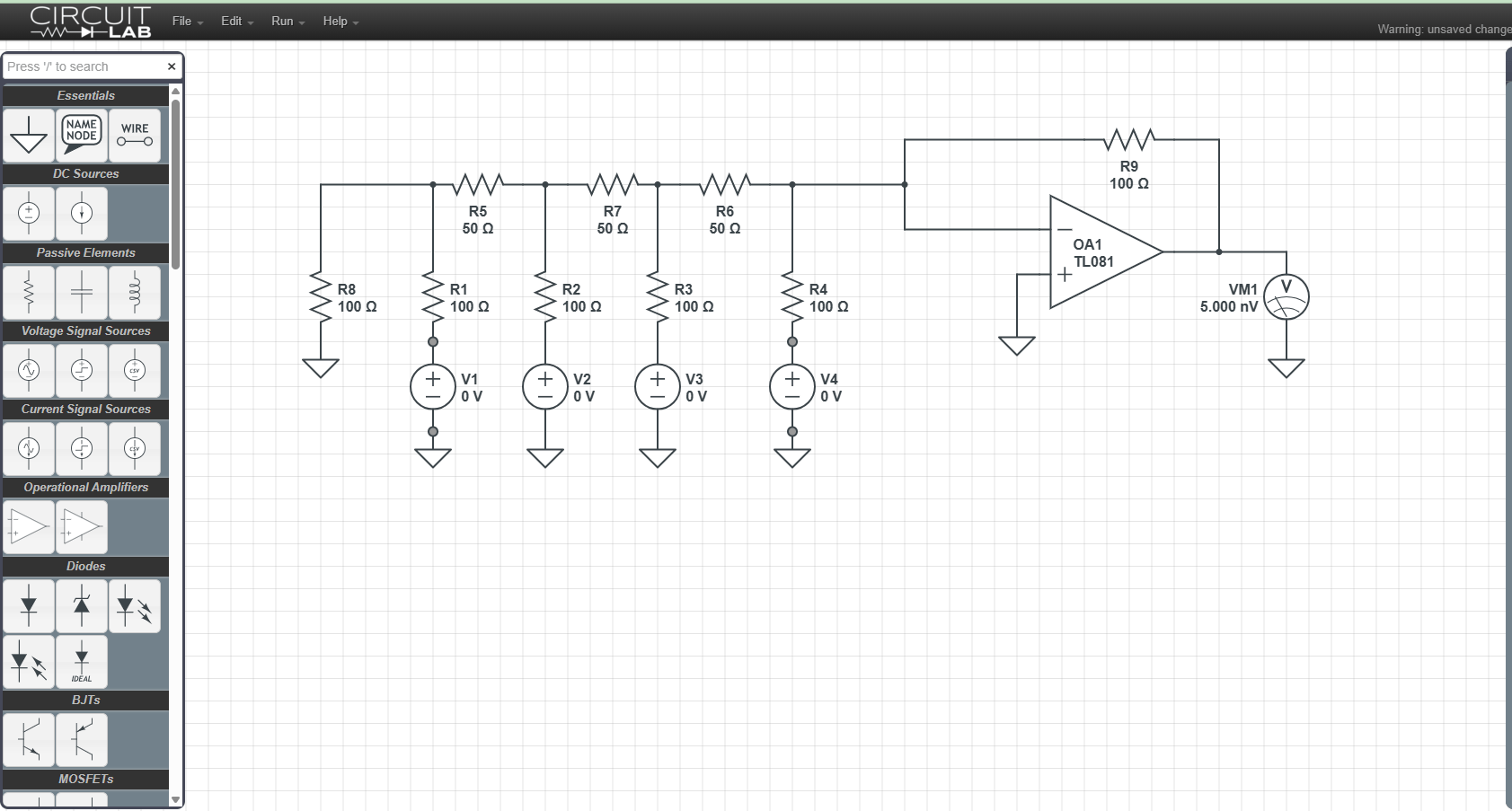
There are four voltages on the bottom. You can adjust all of them. But remember we are building a digital circuit and they can only be ones and zeros (or 3.3 V and 0 V).
The upper right voltmeter is the output voltage.
So let’s play with the numbers
[input voltages] -> out put voltage
- [0,0,0,0] -> 0
- [1,0,0,0] -> -0.125
- [0,1,0,0] -> -0.250
- [1,1,0,0] -> -0.375
- [1,1,1,1] -> -1.875
Think about how a base two number works (*We can adjust with resistors values
| base 10 | base 2 | output* |
| 0 | 0 or 0000 | 0 |
| 1 | 1 or 0001 | -0.125 |
| 2 | 10 or 0010 | -0.250 |
| 3 | 11 or 0011 | -0.375 |
| 4 | 100 or 0100 | -0.500 |
| 5 | 101 or 0101 | |
| 6 | 110 or 0110 | |
| 7 | 111 or 0111 | |
| 8 | 1000 | |
| 9 | 1001 | |



Leave a Reply