These chips are nice but they are psuedo surface mount and a little difficult for students to work with. Never fear, Thorlabs sells these mounted on through out daguhter boards. But let’s see if we can make it ourselves.
My setup getting started with Claude (note this took a day to get all the details right, it sucked):
Installed anaconda (conda) https://www.anaconda.com/download – Note I use Spyder for everything these days. But I went ahead and did a fresh install of Anaconda before I started using Claude Code
Installed a powershell for conda
Created and Activtated a virutal environment for conda for these projects
Installed Claude Code. Note there are two Claude codes. One that sits in its own gui. Its okay, but not much different than just using Claude on the internet. The real power comes using Claude in the powershell.
So here are the commands I gave Claude:
(1) I would like to start a new project. Can you please save everything in the following folder. C:\…\daughtercard1
(2) would you prefer a step file or a CAD DXF file
[[I went to Thorlabs website and downloaded the specs for the part.]]
(3) Can you please read the following file “MTD415L-CAD-DXF.dxf”
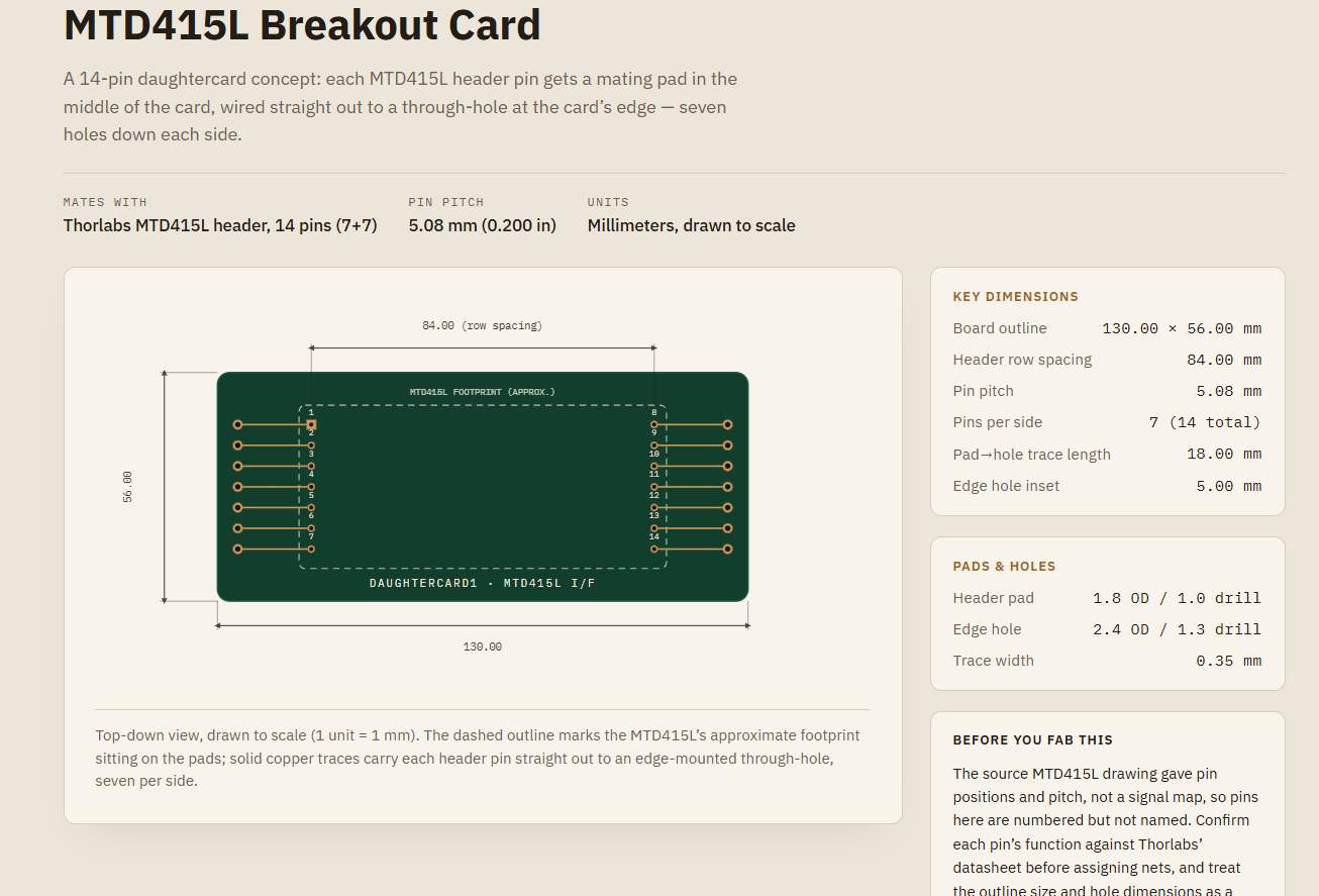
(4) MTD415L has 14 pins, 7 on each side. Can you please generate a daughter board that has a pad for each pin and connects it to a hole on the outside of the card, resulting in 7 holes on each side. Can you please show me a picture of what that looks like?
[[[So Claude generated this picture on the web for me at claude.ai. I just went into my web browser and got a draft of what I want to make.
]]
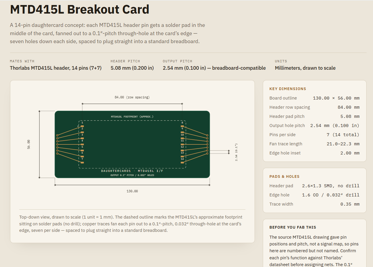
(5) Thank you boss, this is very close. Lets make some changes. a. for the inner connections to the MTD415L, I would like pads to solder to rather holes. b. Can you extend out the output holes so that they fit into a standard breadboard; I believe the hole spacing is 0.1 inches. c. Can you make the output hole size to be 0.032 inches?
[[One the annoying parts is that there is a lot of time waiting while Claude thinks.]]
[[What is interesting here is that chip is really small yet in this picture it looks like it is huge. The specs say the chip is 0.5 ” X 0.75 ” yet on the picture is seems relative to the output holes (which should be bigger)]]
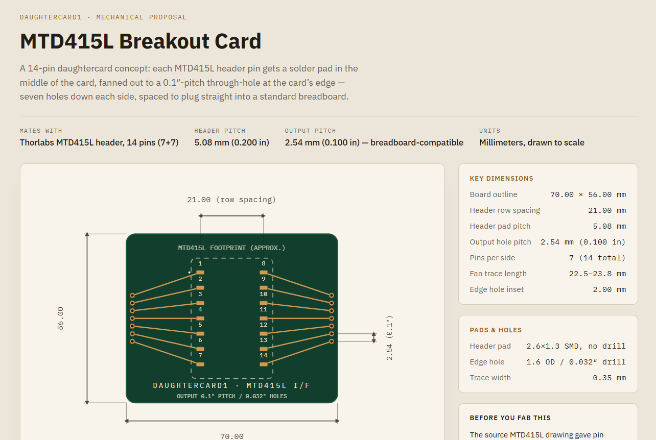
6. Reading the specs, it seems that the Header row spacing should be 21 mm.
[[Claude said: Good catch — that changes the geometry meaningfully (the pads sit much closer together than I had them). Let me fix the row spacing and everything downstream of it (board width, keepout box, fan trace geometry, dimension callouts, and the spec panel).]]
[[Claude talks alot, give you lots of useful information, I am ignoring it here.]]
[[So it seems that it had trouble reading the DXF file and made sense to just give them the dimensions myself.]]
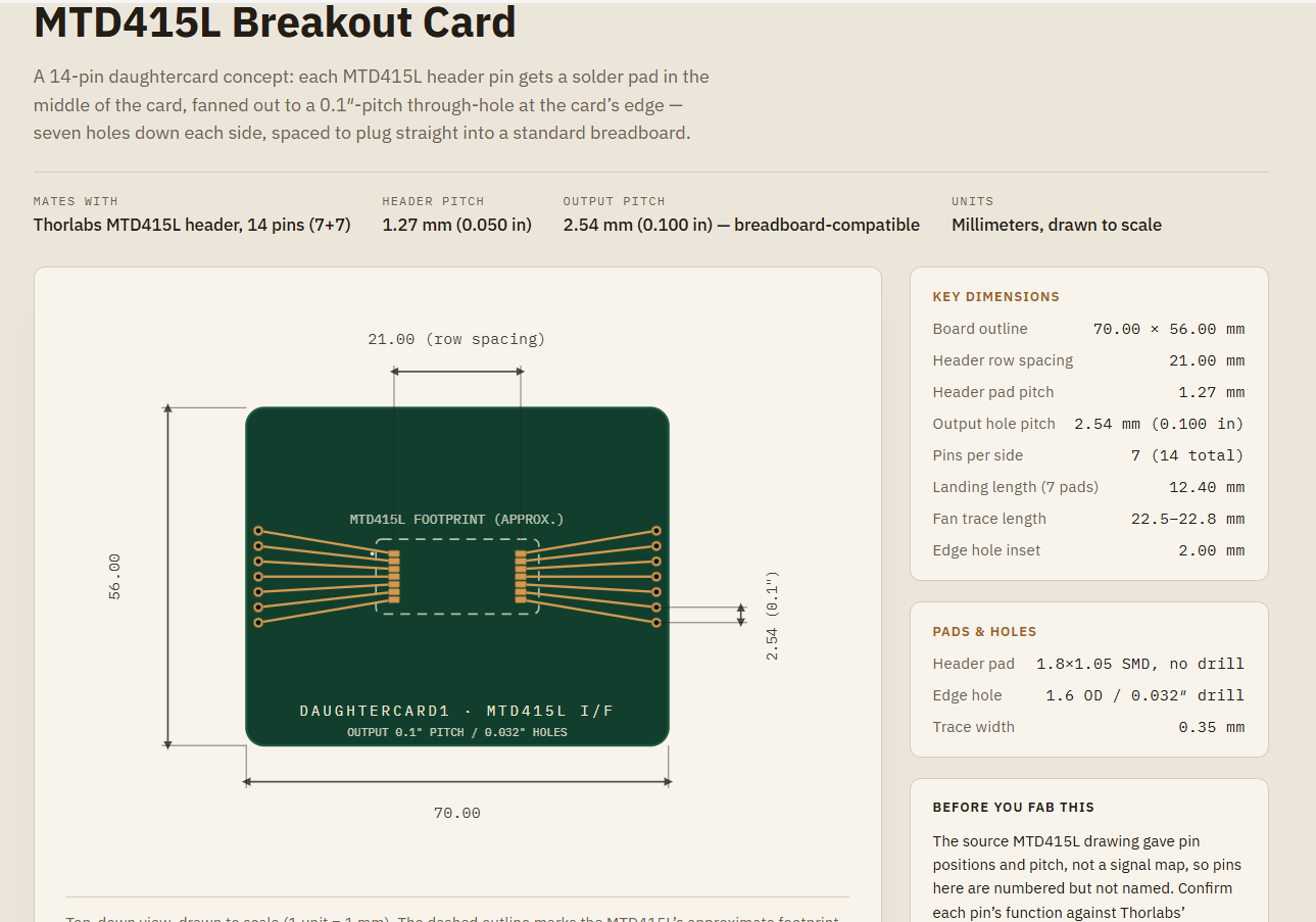
7. okay this better but still not right. Let me give you the dimensions of MLD415L from the spec sheet. The pads one the left side and right side should be 21 mm, the pads should be 1.8mm wide (horzontial) and 1.05 mm (vertical). The spacing between pad vertically is 1.27mm. The total vertical length of the landing is 12.4mm
8. Can you please make this into a Gerber file and G-code file so I can cut it?
While I was working on this, Sara was also working on it and she had a similar project. 🙂 It was nice. We took Sara’s G-code files over to the Nomad3 and printed out a draft of our circuit card…just like that! AMAZING!
We are still learning how to just the Nomad3 so we didn’t get a clean cut yet. They are going to redo today and I expect it to come out perfect!
I was listening to Learning Curve’s podcast yesterday. They had a liberal arts professor saying the had no idea how AI could be useful. We vibe coded a circuit card without touching CAD. AMAZING! CAD programs are great but it really is an experts tool. From my experence its not something that a novice can just do.
I still understand how the circuit works. My student still understands what the circuit does. We are just removing the need for having expertise in the CAD program. It allows up to be more efficent. And get to the good parts of the experiment which really do require understanding.
You might say this is barely a circuit. That’s 100% fair. Its not. But the circuit will come next week. We wanted to do something simple before moving on you know.
Sara made an interesting comment that showed how smart she was. Something to the effect, “Claude made a lot of mistakes and I had to catch them.” That is 100% true!
Cosmic Pathways, Lab for Kids, and many of the other research activities discussed on this website is supported by the National Science Foundation and the Physics Teacher Education Coalition (PhysTEC) under grant no. 2325980. Any opinions, findings, and conclusions, or recommendations expressed in this material are those of the author(s) and do not necessarily reflect the views of the National Science Foundation.
Discover more from Cosmic Pathways
Subscribe now to keep reading and get access to the full archive.





Leave a Reply